 From the Outside:
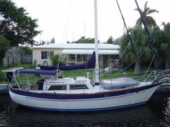
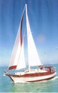
 The Generic Style of the 70's keel and rudder, shown on the left(is not a CSY but very similar in appearance), also similar to Irwin's, Pearson's and other production boats of the time; but like anything else, Design and Technology will evolve.
The design and quality of today's rudders vs. yesterday's' can help you sleep well or just steer better because the technology has entered the arena that before was sometimes only filled with artistic design. Much more is known now in the technical sense and therefore the needs and effects of the outer shape as well as the inner metal skeleton are much better understood.
CSY built a Mack Truck of a rudder. Do not loose this point. In the same years that CSY was using a 2" shaft for it's rudders, one of it's near look-alike competitors named Irwin, was using I believe 1.25" shafting! Big difference. So on shaft size alone, CSY material was massive.
The 2 inch thick Tobin bronze rudder shaft stands out above it's market peers of the day.
However, I feel the rudder's skeleton does have a weak link (in its original design, that lessens the benefit of a 2" shaft).
I offer my thoughts for anyone addressing a broken or damaged rudder or building a replacement as a preventative measure.
A rudder is a wing.
It 'flies' thru water-vertically. The external shape is certainly a 'Part' of a rudders performance -10 knots is not as critical as mach 2..... but moving along at 5-10 there are subtle differences that do make a difference.. The engineering of an item moving thru a liquid is very similar to one moving thru air.
You do your own homework.
-Read what you can and look around at NEW designs of rudders using skegs as well as those that do not...take measurements. I've done this for many years to get my 1000 hamburger degree! :)
( note please that i did it for myself and only recently have put my thoughts in print for others to think about.)
The aft swept bottom of the original CSY rudder seems to have little to do with engineering but more to do
 with how it looked drawn on paper. My 2 cents.
If any of you wish to comment or debate this item or add what they feel is different; you can do that below; in the request for: COMMENTS
Not to be forgotten, most of the CSY rudders have seemed to work fine over the years and I have never heard of anyone saying the CSY rudder did not handle the boat just fine.
Peter Rabbits new rudder skeleton on left. Paul had the arms of the rudder "welded", completely around the rudder shaft.
The loads imposed at the bottom of the original CSY rudder, are transferred up to the gudgeon support at the bottom of the skeg. These loads are increased by the longer CSY's horizontal length at the bottom of the rudder.
I'm including here some old sketches of measurements I took , that I felt "I" needed to consider- before replacing my original rudder. It's my "armchair" engineering...do you own thinking!
Early drawing-Highlighted for emphasis: A copy of this was passed on to show OPTIONS I thought were possible and MODIFICATIONS to the original design that I incorporated into my new rudder in 1994.
 RUDDER REDUX:
CROPPED FROM PAGE 87 OF SAIL MAGAZINE, APRIL 2008. IT EMPHASIZES MODERN DESIGN BENEFITS AND ADDED HELP FROM TYING IN A PORTION OF THE FORWARD PART OF RUDDER BELOW THE GUDGEON.
***2 things to note in this new article : 1. clip the trailing section-bringing loads closer in towards the internal shafting to help carry loads, and
2. incorporate a bit of the skeg into rudder design. A fellow CSY owner, Joe Silvernail had modified his this way and said it was a Plus! Thats why I had 'considered' it in 1994. Next time!

I tried to come up with, what I thought was a modernized/more efficient design and one that might also lessen the loads on the gudgeon or at least not increase them. The loads of the bottom triangular tail(Orange-ish color) is clipped off and then this area is flipped upside down and added to the upper trailing edge of the rudder as shown above in the drawing.
The blue outline is what I ended up using as the final shape for my vessel, Memory Rose.
Photo 3 is a scan of original sketches that I took over to Scott Penfield years ago when he was trying to figure out what he was dealing with to rebuild Chanticleer's previously modified rudder.
click on any drawing to enlarge
The highlighter colors, indicate original dimensions as well as some options available when building a New Rudder.
---It should be obvious to a CSY owner, what the Original shape of the rudder looks. It's highlighted. [ rudder in Orange / skeg in Pink. ]
---Blue is what I built. The more symetrical shape does several things. It decreases the loads on the Gudgeon support on the bottom, centering the load between the gudgeon and the Rudder Bearing at the hull. It also makes steering easier. Having to work with the Skeg as part of the overall design of a 'Wing", eliminating the extended lower trailing edge, allowed me to built closer to shape suggested for an aircraft wing. The rudder is a WING-moving thru water. It should be designed to operate as such.
After reading what "I" could, and for a few years measuring boat rudders whenever I could get into a boatyard to do so, as well as talking to many builders and a few N.A.'s(naval architects) I was convinced that since rudders were going in a 'certain' direction over the last 30 years, that I would follow the mindset. I did not invent this, but I did try to understand their 'thinking'.
While going thru a 'tour' of a major local sailboat builder here in St.Pete/Clearwater(Catalina/Morgan), I questioned them on the internals of their rudders. Also, inspected an 'aftermarket' builder of rudders that used to build here in the same area, (Foss Foam, ). I called 2 major N.A.'s and felt comfortable in what I had designed for Memory Rose, my CSY 44 Pilothouse sailboat.

We built a new rudder for our CSY Memory Rose, in 1994- as a precautionary measure. Several other owners have done the same, after having visited our boat and examiniming our efforts and conclusions. They 'digested' what I did then added their own mindset to their new rudder's design. I offer an intro to their designs here as well.

CSY Original Rudder skeleton-on left as well as a CSY original photo and description of the rudder shown as the Mold....click to enlarge.
I decided to attempt to do what the Major Sailboat builders were doing, welding a flat plate to the aft of the rudder shaft.... with a few additional tweaks. A problem with 'Their' Designs, as I saw it, was the concept requires too much welding---that will bend even a 2" shaft.
 Heat warps Stainless Steel! I had to take the warping out which is a difficult process.
Green Rectangle at right is the rudder of Memory Rose. The bottom triangle was removed and flipped up-as drawing above has shown- and rudder and skeg lengthened 7" to increase size by 14%.
Luckily, I was able to tweak my shaft after welding to take out a .020" warp incurred during welding and then added special UHMP(ulta high molecular plastic)bearings-very slippery stuff- in a reamed out gudgeon to make sure everything slips well; mentioning to ALL visitors to our boat, the potential problem of welding a large plate on the back of a rudder shaft. There are tricks if you do, but be aware!
John Nunenmaker's rudder shaft shown below(bright and shiney! now under construction)-uses a what I think is the answer....a "keyway" to hold the aft facing horizontal support arm and later the vertical support plate, with only a "tack weld" to hold all of it to the key!-no major weldments!
The key cannot move up as the keyway is short and the arms are press fit using hot/cold application techniques.


[Note below: CSY used a piece of Flat Stock slipped into a milled out hole in the rudder and then-if you have good eyes, can see that 2, .375" pins were inserted perpendicular to the flat bar to hold it.................too much material removed from the shaft..this is where the rudder will break (at the upper bar) if you back into anything.
 CSY factory, used Bronze,(above) then machined out material for(3)...... 3/8"H x 2"L slots for the 3 pieces of bronze flat bar to exit the shaft. It was the UPPER bar that will be the first to fail if you accidentally back into a sand bar or mud flat too hard or. The Flat 2" bar was inserted into a milled out portion of the rudder shaft and then the shaft was drilled for 2- 3/8" dowls or pins to hold the flat bar in place.
 Removing that bronze material for the slot as well as material perpendicular to those ( 2)-3/8" dowl holes, severely weakens the rudder at the junction of the "upper flat bar and rudder shaft." The machining removes almost HALF the material and strength of the original 2" shaft.
Ok, if you do not back into anything or overstress the rudder by maybe letting the wheel go when in reverse and having the rudder slam into one of it's stops, you probably will be fine. I am writing this as this is where CSY rudders have failed-to my knowledge. If you are concerned, you have benefit of the experience/thoughts of others. In my case, I know it is not difficult to screw up and back into some mud or sand in tight quarters. I have already screwed up and released the rudder while backing up and heard it slam over. I intend to set my rudder to windward when hove to and if I ever have to use my sea anchor, the rudder will be locked to one side taking on much loading. I want to be able to count on as much safety as I can build into my boat before I need it. Did it with everything above water, no sense ignoring what's below.
I first learned of this problem from Bob Jefferies, years ago when he snapped his shaft while visiting a small reef in Belize. HE, fixed his shaft while at anchor but I truly doubt many of us would have the abilities or mindset of old Bob. He was in his 70's and so was his crew-but they were men of exceptional ability-sailors. It's best if his ideas are done as "preventative measures, ashore and in a boat yard but..". The 3 bolt idea (below), can bring you home so why not do it now instead, as a 'supportive' measure that could be taken by anyone during their next haul out...just to help. Just an idea if all seems OK, now.
At the top of the rudder's horizontal glass work [and the apparent place that the rudder shaft will most likely give way (7" down),] pre-drill a few (3), 3/8" to 1/2" holes from port to starboard thru the rudder. You might be able to interpret well the distance by the photos offered above. Since the Original Rudder is filled with a slurry of polyester resin, it is hard as a brick. The bolts will tie the fiberglass portion of the rudder to the internal Bronze skeleton. This will help or maybe alleviate the loads on the 'weak' point that "I" feel has been the culprit of rudder failure.


No comments:
Post a Comment